Test 2 Mechanical: SolidWorks CAD – Intermediate Level
Advanced mechanical design and parametric modeling under SolidWorks as part of the Tekbot Robotics Challenge 2025.
🔹 Introduction
This intermediate level CAD test under SOLIDWORKS, carried out as part of the Tekbot Robotics Challenge 2025, allowed us to put into practice several key skills:
- Creation of parametric and adaptable parts
- Modification of existing geometries using advanced techniques
- Addition of 3D features such as pockets
- Realization of a complete assembly with mass and center of gravity control
The test is divided into four phases: three part modeling steps, followed by a final assembly exercise.
All modeling is performed in the MMGS environment (millimeter, gram, second) with two decimal precision. The material used is AISI 1020 steel, with density 0.0079 g/mm³.
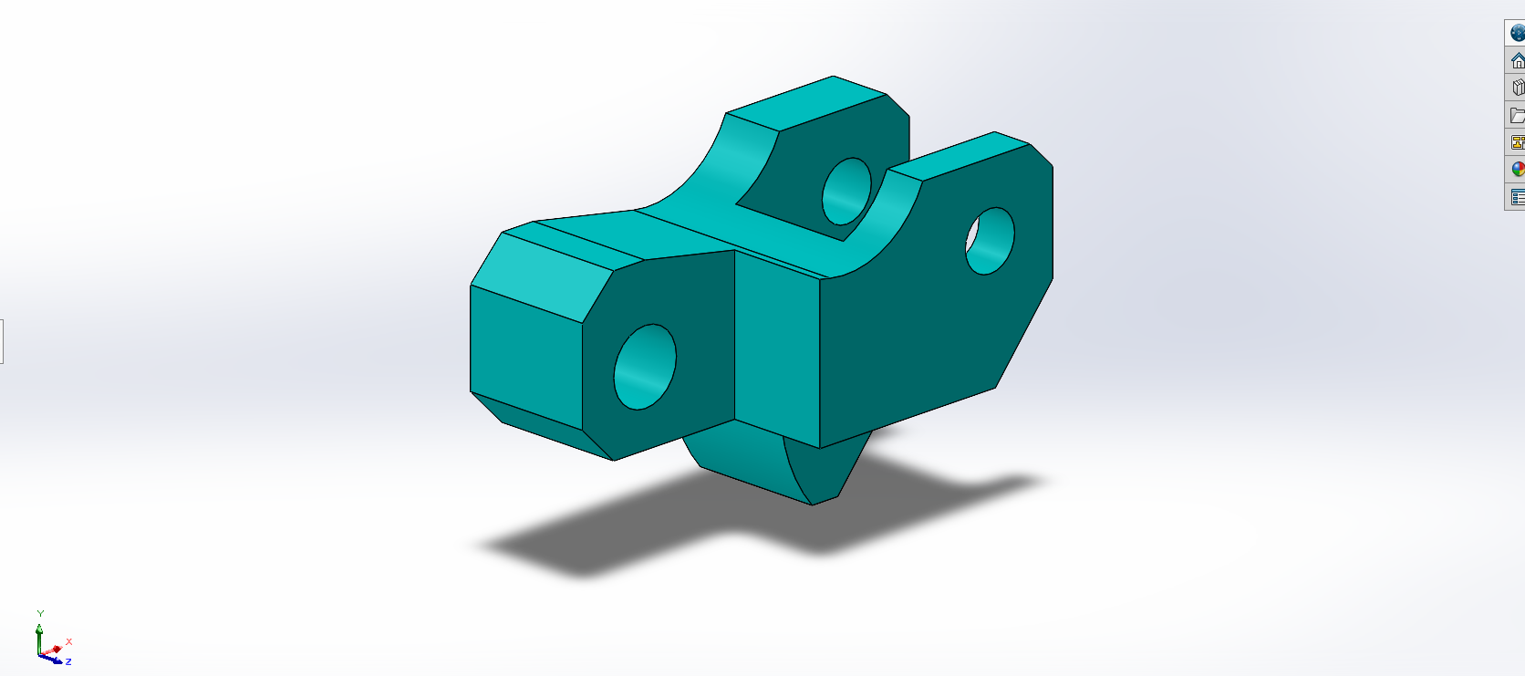
🔧 Part I – Parametric part design
a) Parameters: A = 81.00 ; B = 57.00 ; C = 43.00
- File: Part1(a).SLDPRT
- Obtained mass: 977.95 g
🖼️ Part visualization
.png)
b) Parameters: A = 84.00 ; B = 59.00 ; C = 45.00
- File: Part1(b).SLDPRT
- Obtained mass: 1068.75 g
🖼️ Part visualization
.png)
Used features
- 2D (Sketch): line, arc, circle, smart dimension, geometric relations
- 3D (Features): boss/base by extrusion, material removal by extrusion, fillet, hole wizard from sketch
✂️ Part II – Part modification
- Updated parameters: A = 86.00 ; B = 58.00 ; C = 44.00
- Direct dimension modification in the feature tree
- Addition of material removal by extrusion
- File: Partie 2.SLDPRT
- Obtained mass: 628.18 g
🖼️ Part visualization
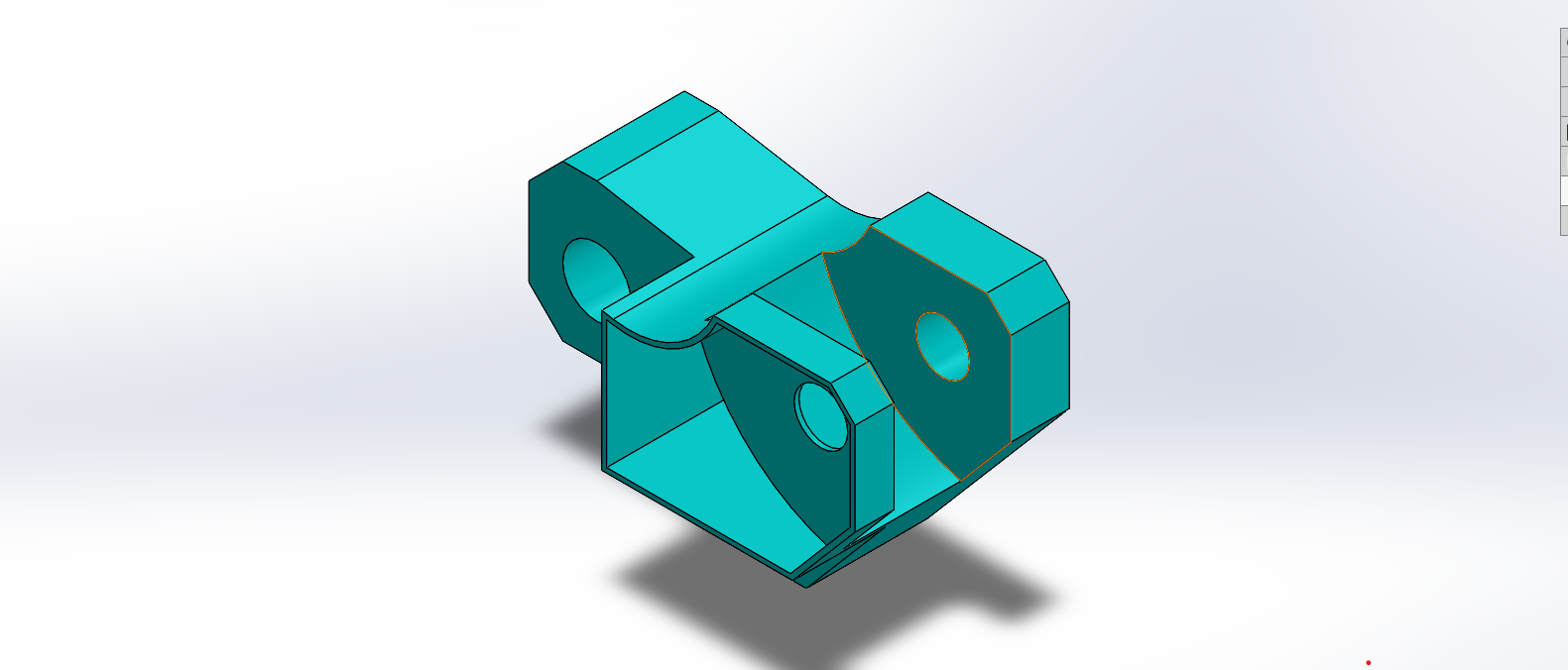
🧩 Part III – Pocket addition
- Addition of a lateral pocket to make the part asymmetric
- Creation of a rectangular sketch on a lateral face then material removal by extrusion
- File: Partie 3.SLDPRT
- Obtained mass: 432.58 g
🖼️ Part visualization
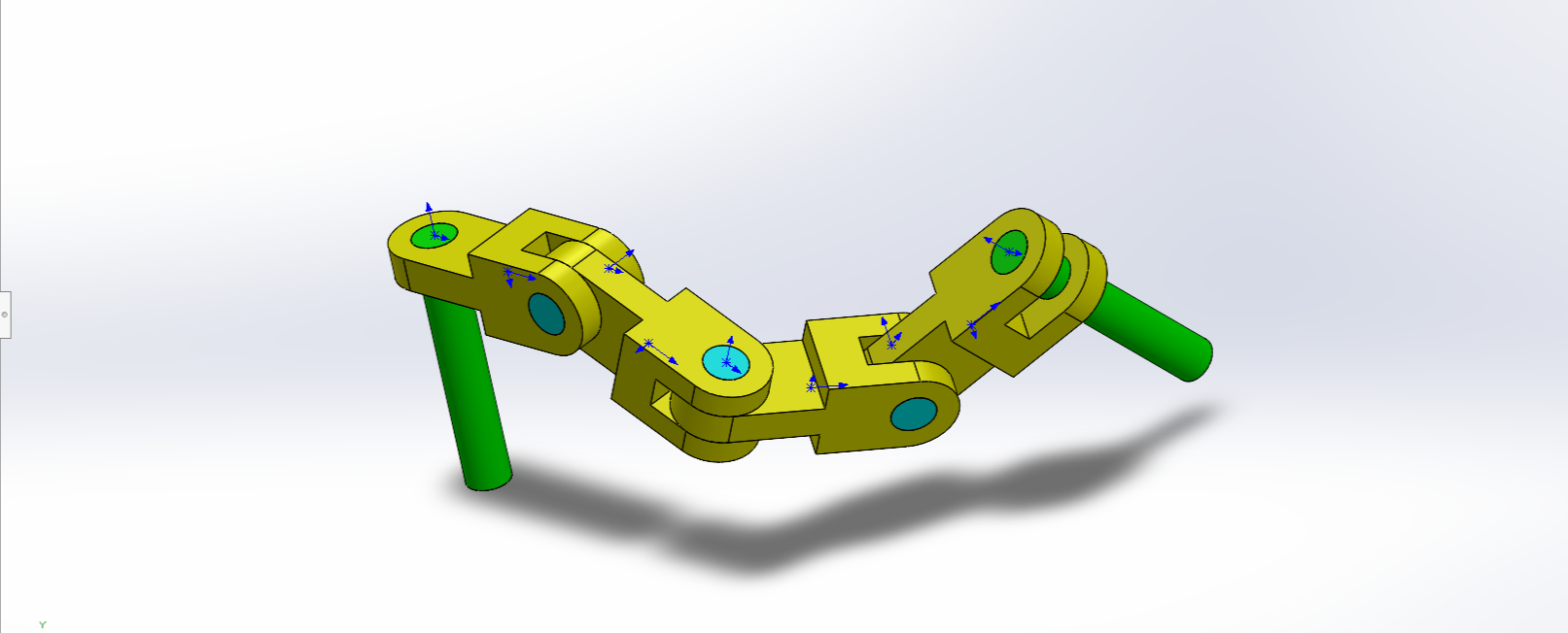
🛠️ Assembly – Chain links
- Download and extract the ZIP file containing the parts
- Import parts into SOLIDWORKS
- Apply necessary constraints: concentricity, coincidence and origin alignment
Case a)
- Parameters: A = 25° ; B = 125° ; C = 130°
- File: Assem3.SLDASM question (a).SLDASM
- Center of gravity (in mm):
- X = 348.66
- Y = -88.48
- Z = -91.40
🖼️ Assembly visualization
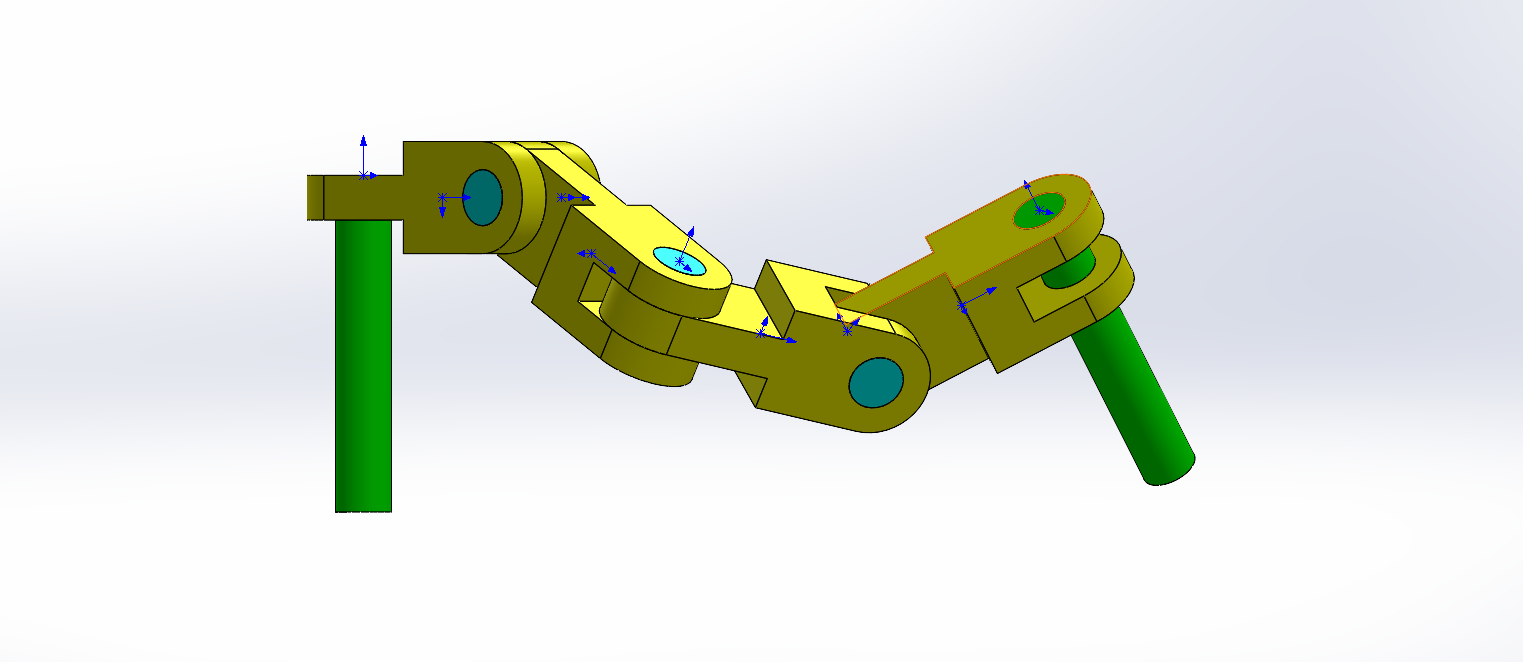
Case b)
- Parameters: A = 30° ; B = 115° ; C = 135°
- File: Assem3.SLDASM question (b).SLDASM
- Center of gravity (in mm):
- X = 327.67
- Y = -98.39
- Z = -102.91
🖼️ Assembly visualization
📥 Source files download
All SOLIDWORKS files of this project are grouped in a ZIP archive ready to download.
Complete archive
Contains all parts and all assemblies.
📁 Archive contents
| • Part1(a).SLDPRT | • Partie3.SLDPRT |
| • Part1(b).SLDPRT | • Assem3(a).SLDASM |
| • Partie2.SLDPRT | • Assem3(b).SLDASM |
🏆 Optional challenge
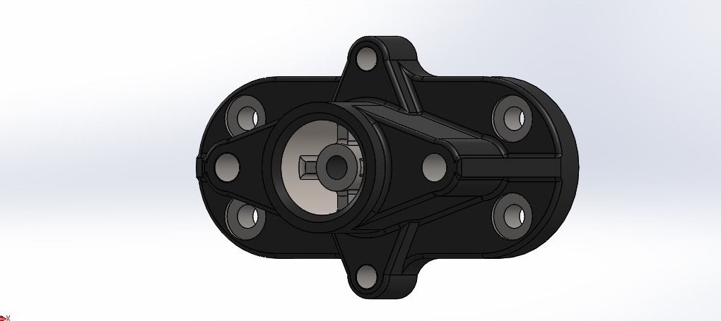
We present here the complete modeling of the optional challenge.
For this challenge, the part was modeled using basic features as well as advanced SolidWorks features such as boss, rib, material removal by extrusion, etc., while respecting the MMGS system and the specified material (AISI 1020 steel).
3D view of the part
🖼️ 3D view of the challenge part
✅ Conclusion
- Mastery of parametric modeling
- Ability to modify and enrich 3D features
- Precise management of assembly relations
- Rigorous control of mass and center of gravity
All steps have been carefully documented and saved in separate files (.SLDPRT and .SLDASM).