Test 2 ELectronic: Communication Test - The Black Box
Real-time motion data recording and transmission system using the MPU6050 sensor in a cubic enclosure.
Duration: 1 week
Introduction
In aerospace, automotive, and railway sectors, black boxes are essential for recording operational data. Inspired by these systems, we designed a device capable of recording and transmitting real-time motion data of a robot using an MPU6050 sensor (accelerometer + gyroscope) integrated into a cubic box.
Test objectives
- Implement an inertial data acquisition system (MPU6050)
- Transmit data via I2C bus to a control station
- Display data in real time on an LCD screen
- Use ATmega328P microcontrollers without Arduino boards
- Document PCB design and ensure professional presentation
Used components
2 × ATmega328P
Core of the system, these 8-bit microcontrollers handle:
- I2C communication between modules
- Sensor data processing
- LCD display control
Specifications: 32KB Flash, 2KB SRAM, 16MHz
1 × MPU6050 module
6-axis sensor (gyroscope + accelerometer) used for:
- Spatial orientation detection
- Sudden movement measurement
- Earth gravity reference
I2C Communication (address 0x68)
1 × LCD 16x2 screen
Data visualization interface:
- Displays data in real time
- Controlled via I2C interface
- Typical address: 0x27 or 0x3F
- Consumption: ~1mA
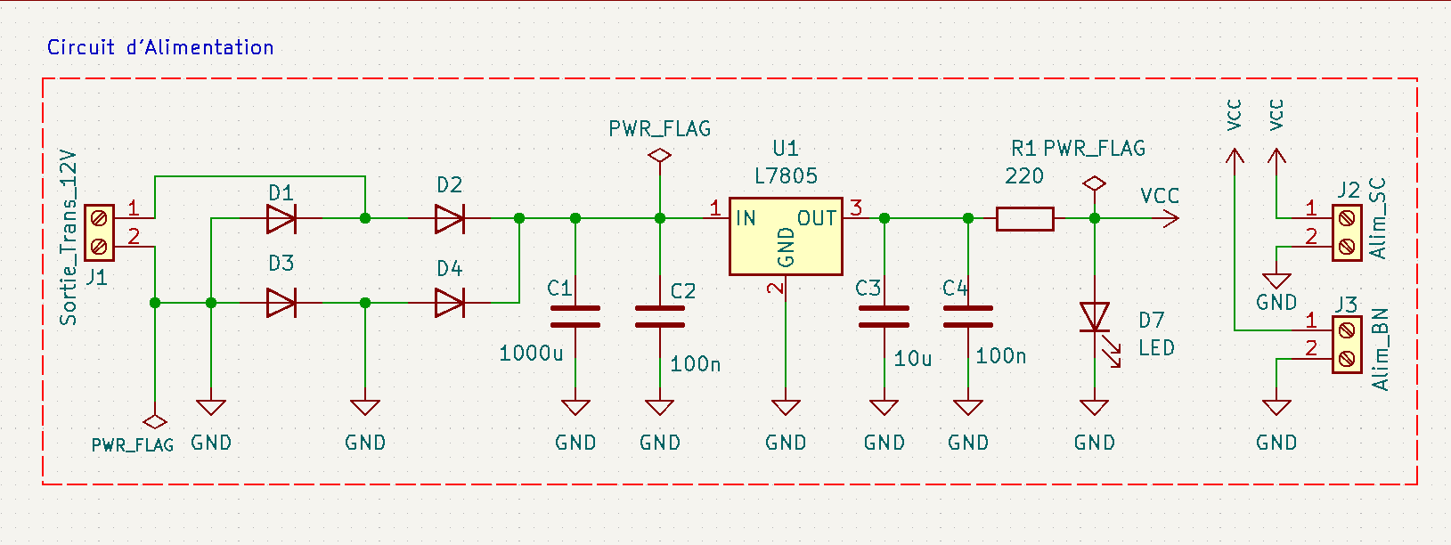
1 × 5V voltage regulator
Stabilizes power supply:
- Protects sensitive components
- Type: LM7805
- Max current: 1A (with heat sink)
System architecture
The system is distributed in two modules:
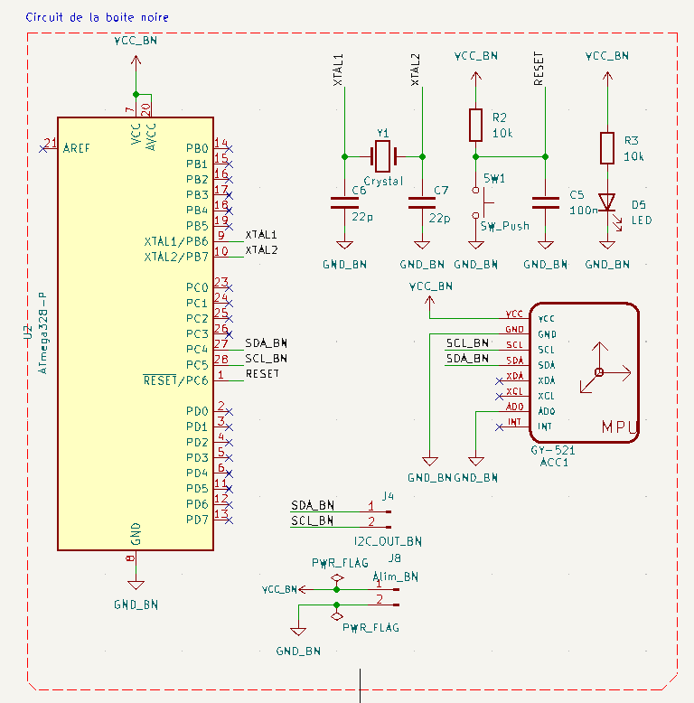
- Sensor module (black box): contains the I2C master ATmega328P and MPU6050
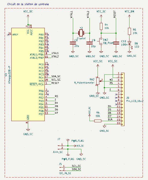
- Control station: contains the I2C slave ATmega328P and LCD screen
Electronic schematics (made with KiCad)
Circuits were designed with KiCad for each subsystem of the project.
Power supply schematic
Black box schematic
Control station schematic
KiCad files download
Download all KiCad source files including schematics and PCBs of the project:
📥 Download complete KiCad folder (RAR)
Printed circuits (PCB)
Physical support of the circuit: Custom PCB for each module: power supply, black box and control station.
Power supply board
2D view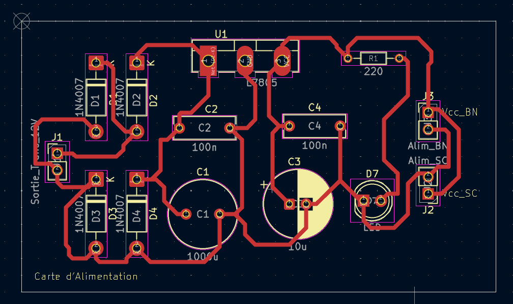
3D view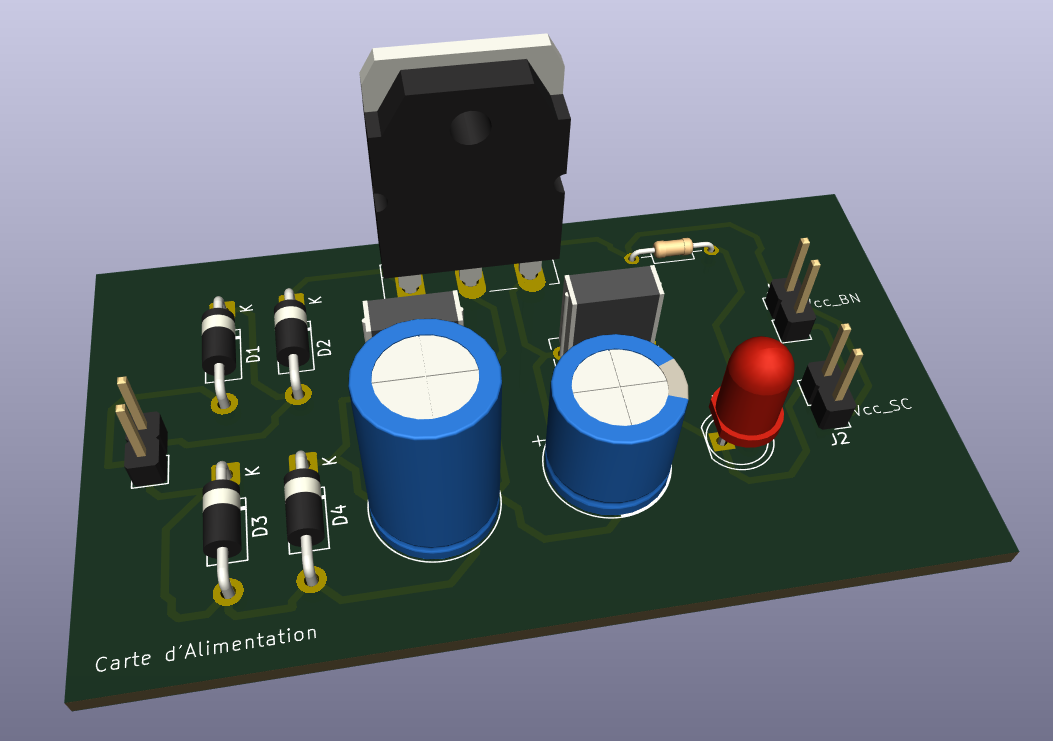
Black box board
2D view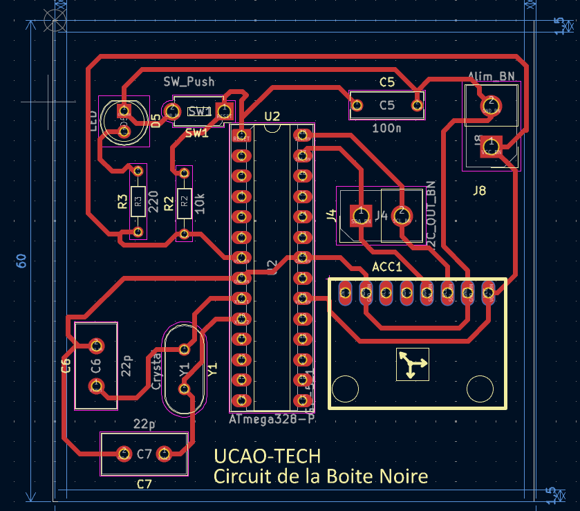
3D view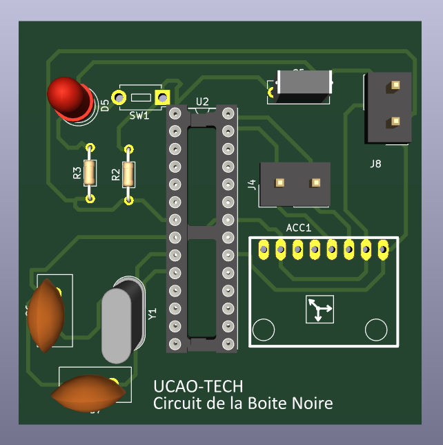
Control station board
2D view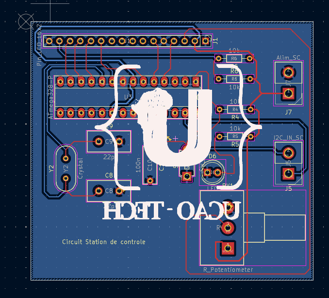
3D view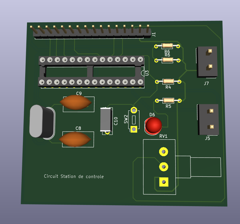
Proteus simulation
Since the MPU6050 module is not available in the official Proteus library, we simulated its behavior by directly injecting constant data into the master microcontroller (ATmega328P). This allows verifying the I2C bus operation, data transmission and LCD display.
Simulation folder structure
📁 Simulation_Proteus_Black_Box
├── 📁 master
│   ├── master.ino
└── 📁 slave
    └── slave.ino
Simulation project download
📥 Download simulation project (.rar)
Simulation demonstration video
See the Proteus simulation demonstration video
Code
Black box side (I2C Master with MPU6050)
#define F_CPU 16000000UL
#include <avr/io.h>
#include <util/delay.h>
#include <avr/interrupt.h>

#define MPU6050_ADDR 0x68
#define SLAVE_ADDR 0x20

// === I2C Master ===
void I2C_Init() {
    TWSR = 0x00;
    TWBR = 72; // 100kHz at 16MHz
}

void I2C_Start() {
    TWCR = (1 << TWINT) | (1 << TWSTA) | (1 << TWEN);
    while (!(TWCR & (1 << TWINT)));
}

void I2C_Stop() {
    TWCR = (1 << TWINT) | (1 << TWSTO) | (1 << TWEN);
    _delay_us(10);
}

void I2C_Write(uint8_t data) {
    TWDR = data;
    TWCR = (1 << TWINT) | (1 << TWEN);
    while (!(TWCR & (1 << TWINT)));
}

uint8_t I2C_Read_ACK() {
    TWCR = (1 << TWINT) | (1 << TWEN) | (1 << TWEA);
    while (!(TWCR & (1 << TWINT)));
    return TWDR;
}

uint8_t I2C_Read_NACK() {
    TWCR = (1 << TWINT) | (1 << TWEN);
    while (!(TWCR & (1 << TWINT)));
    return TWDR;
}

// === MPU6050 ===
void MPU6050_Init() {
    I2C_Start();
    I2C_Write(MPU6050_ADDR << 1);  // Write mode
    I2C_Write(0x6B); // PWR_MGMT_1
    I2C_Write(0);    // Wake up
    I2C_Stop();
}

int16_t MPU6050_ReadAxis(uint8_t regH) {
    I2C_Start();
    I2C_Write(MPU6050_ADDR << 1);  // Write
    I2C_Write(regH);               // Register to read
    I2C_Start();
    I2C_Write((MPU6050_ADDR << 1) | 1); // Read
    uint8_t high = I2C_Read_ACK();
    uint8_t low = I2C_Read_NACK();
    I2C_Stop();
    return (int16_t)(high << 8 | low);
}

int main() {
    DDRB |= (1 << PB5); // Debug LED
    I2C_Init();
    MPU6050_Init();

    while (1) {
        int16_t accX = MPU6050_ReadAxis(0x3B);
        int16_t accY = MPU6050_ReadAxis(0x3D);
        int16_t accZ = MPU6050_ReadAxis(0x3F);

        // Send data to slave
        I2C_Start();
        I2C_Write(SLAVE_ADDR << 1); // Slave
        I2C_Write(accX >> 8); I2C_Write(accX & 0xFF);
        I2C_Write(accY >> 8); I2C_Write(accY & 0xFF);
        I2C_Write(accZ >> 8); I2C_Write(accZ & 0xFF);
        I2C_Stop();

        PORTB ^= (1 << PB5);
        _delay_ms(300);
    }
}
Control station side (I2C Slave + LCD 4-bit)
#define F_CPU 16000000UL
#include <avr/io.h>
#include <avr/interrupt.h>
#include <util/delay.h>
#include <stdio.h>

#define LCD_PORT PORTD
#define LCD_DDR DDRD
#define RS PD0
#define EN PD1

volatile int16_t accX, accY, accZ;
volatile uint8_t data_received = 0;

// === LCD 4-bit functions ===
void LCD_Command(uint8_t cmd) {
    LCD_PORT = (LCD_PORT & 0x0F) | (cmd & 0xF0);
    LCD_PORT &= ~(1 << RS);
    LCD_PORT |= (1 << EN);
    _delay_us(1);
    LCD_PORT &= ~(1 << EN);
    _delay_us(200);

    LCD_PORT = (LCD_PORT & 0x0F) | (cmd << 4);
    LCD_PORT |= (1 << RS);
    LCD_PORT |= (1 << EN);
    _delay_us(1);
    LCD_PORT &= ~(1 << EN);
    _delay_ms(2);
}

void LCD_Char(char data) {
    LCD_PORT = (LCD_PORT & 0x0F) | (data & 0xF0);
    LCD_PORT |= (1 << RS);
    LCD_PORT |= (1 << EN);
    _delay_us(1);
    LCD_PORT &= ~(1 << EN);
    _delay_us(200);

    LCD_PORT = (LCD_PORT & 0x0F) | (data << 4);
    LCD_PORT |= (1 << RS);
    LCD_PORT |= (1 << EN);
    _delay_us(1);
    LCD_PORT &= ~(1 << EN);
    _delay_ms(2);
}

void LCD_Init() {
    LCD_DDR = 0xFF;
    _delay_ms(50);
    LCD_Command(0x02);
    LCD_Command(0x28);
    LCD_Command(0x0C);
    LCD_Command(0x06);
    LCD_Command(0x01);
}

void LCD_Print(char *str) {
    while (*str) {
        LCD_Char(*str++);
    }
}

// === ISR for I2C reception ===
ISR(TWI_vect) {
    static uint8_t buffer[6];
    static uint8_t index = 0;

    switch (TWSR & 0xF8) {
        case 0x60: // Slave address received (Write)
            index = 0;
            TWCR |= (1 << TWEA) | (1 << TWINT);
            break;
        case 0x80: // Data received
            buffer[index++] = TWDR;
            if (index >= 6) {
                accX = (buffer[0] << 8) | buffer[1];
                accY = (buffer[2] << 8) | buffer[3];
                accZ = (buffer[4] << 8) | buffer[5];
                data_received = 1;
                index = 0; // Reset after reception
            }
            TWCR |= (1 << TWEA) | (1 << TWINT);
            break;
        default:
            TWCR |= (1 << TWEA) | (1 << TWINT);
            break;
    }
}

int main() {
    DDRB |= (1 << PB1); // Debug LED for reception signal
    LCD_Init();

    // I2C as slave
    TWAR = (0x20 << 1);  // Slave address 0x20
    TWCR = (1 << TWEA) | (1 << TWEN) | (1 << TWIE);
    sei(); // Global interrupts

    char text[16];

    while (1) {
        if (data_received) {
            LCD_Command(0x80); // Line 1
            sprintf(text, "X:%4d Y:%4d", accX, accY);
            LCD_Print(text);

            LCD_Command(0xC0); // Line 2
            sprintf(text, "Z:%4d", accZ);
            LCD_Print(text);

            PORTB ^= (1 << PB1);  // Blink LED for debugging
            data_received = 0;
        }
    }
}
Explanation: Simulation vs Reality
Although the Proteus simulation is close to reality, some differences may exist due to:
- Idealized component models in Proteus
- Absence of electrical noise and other interferences
- Slightly different microcontroller behavior in a simulated environment
Demonstration video
A video showing the system operation in reality is available here:
Constraints and recommendations
- Ensure all components are properly powered.
- Check I2C connections (SDA, SCL) between modules.
- Use appropriate pull-up resistors for the I2C bus.
- For extended tests, consider an enclosure to protect the electronics.
Evaluation criteria
- System functionality (data acquisition and transmission)
- Accuracy of displayed data
- Robustness of I2C communication
- Quality of documentation and PCB
Technical references
Links to technical documents (datasheets) used in this project:
- ATmega328P – Datasheet (Microchip)
- MPU6050 – Datasheet (TDK InvenSense)
- LCD HD44780 – Datasheet
- LM7805 – Datasheet (STMicroelectronics)
Conclusion
This project allowed to:
- Understand and use the I2C protocol for communication between microcontrollers and sensors.
- Design printed circuits (PCB) for embedded applications.
- Integrate inertial sensors in robotic systems for motion and orientation detection.
Future improvements could include:
- Adding external memory for data recording.
- Using a battery with power management for greater autonomy.
- Implementing an automatic calibration system for the MPU6050.