Test 1 Mechanical: SolidWorks CAD – Beginner Level
Assessment of fundamental skills in Computer-Aided Design (CAD) through 3D part modeling and mechanical assembly under SolidWorks.
Objective
This test evaluates our fundamental skills in CAD using SolidWorks software. The objective is to create, from dimensioned sketches, a set of functional 3D parts respecting material, mass and geometry constraints, then perform a functional mechanical assembly with center of gravity calculation.
Modeled parts
We designed four individual parts from 2D plans, using the basic tools of the software.
Methodology used
- 2D Sketches: rectangles, circles, polygons, construction lines
- 3D Features:
- Boss/Base by extrusion
- Material removal by extrusion
- Fillets (radii)
- Symmetry
- Sketch constraints: horizontal, vertical, tangent, coincident, symmetric
- Unit system: MMGS (mm, gram, second)
- Decimals: 2 digits after the decimal point
- Holes: all through unless otherwise indicated
Part details
| Part | Material | Density (g/mm³) | Obtained mass |
|---|---|---|---|
| Part 1 | AISI 1020 Steel | 0.0079 | 2850.16 g |
| Part 2 | Aluminum 1060 | 0.0027 | 279.77 g |
| Part 3 | AISI 1020 Steel | 0.0079 | 1633.25 g |
| Part 4 | Aluminum 1060 | 0.0027 | 297.29 g |
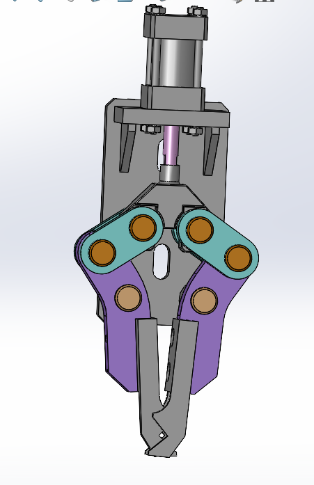
Mechanical gripper assembly
The mechanical gripper assembly was performed under SolidWorks from the components provided in the .zip file. The objective was to correctly assemble all parts while respecting the degrees of freedom necessary for the gripper's operation, particularly its opening and closing via the cylinder action.
Used parts
- Cylinder body
- Cylinder rod
- Cylinder end
- Links (left and right)
- Link pins
- Jaw supports (left and right)
- Jaws (left and right)
- Circlips (locking elements)
- CHC screws M5x25
- Jaw support pin
Main assembly steps
Base fixation
- The sub-assembly containing the cylinder (body + rod + end) was inserted and fixed as reference (immobile component).
Link assembly
- The two links were inserted and constrained with:
- Concentric constraint: alignment of rotation axes with cylinder holes
- Symmetry constraint: identical and opposite movement on both sides via the top plane
- The two links were inserted and constrained with:
Addition of supports and jaws
- Each jaw support was assembled with its corresponding link:
- Concentric: between the support hole and the link
- Coincident: to fix the lateral position
- The jaws were fixed on the supports with the same types of constraints.
- Each jaw support was assembled with its corresponding link:
Insertion of link pins
- The pins were used instead of screws, with the following constraints:
- Concentric: between the pin and the through holes
- Coincident: between the pin head and the contact surface
- The pins were used instead of screws, with the following constraints:
Placement of circlips
- The circlips were inserted to mechanically lock the pins, without adding unnecessary overconstraints.
Used constraints
| Constraint type | Use |
|---|---|
| Concentric | Axis alignment (holes and pins) |
| Coincident | Contact between flat faces |
| Symmetry | Movement synchronization |
Center of gravity analysis
The center of gravity analysis allows better understanding of the gripper's balancing in different operating positions. It was performed under SolidWorks after finalizing the assembly.
a) Minimum position of the cylinder rod
In this position, the cylinder rod is fully retracted into the body, corresponding to the closed gripper state.
Center of gravity coordinates (in mm):
- X = -29.15
- Y = 0.16
- Z = 19.93
b) Maximum position of the cylinder rod
The rod is fully extended, corresponding to the open gripper state.
Center of gravity coordinates (in mm):
- X = -25.78
- Y = 0.06
- Z = 19.93
Problems encountered and solutions
| Problem | Probable cause | Applied solution |
|---|---|---|
| Overconstraints of certain parts | Excessive or contradictory constraints | Removal of redundant constraints and verification of degrees of freedom |
| Error when applying symmetry | Poor selection of faces or reference plane | Correct reapplication with selection of both faces and the top plane |
| Blocking of gripper movement | Too many fixed parts or locked constraints | Application of only essential constraints (coincident and concentric) |
| Circlips blocking movement | Too many constraints applied to circlips | Addition of only one constraint (e.g. concentric) to avoid blocking |
Graphical resources and SolidWorks files
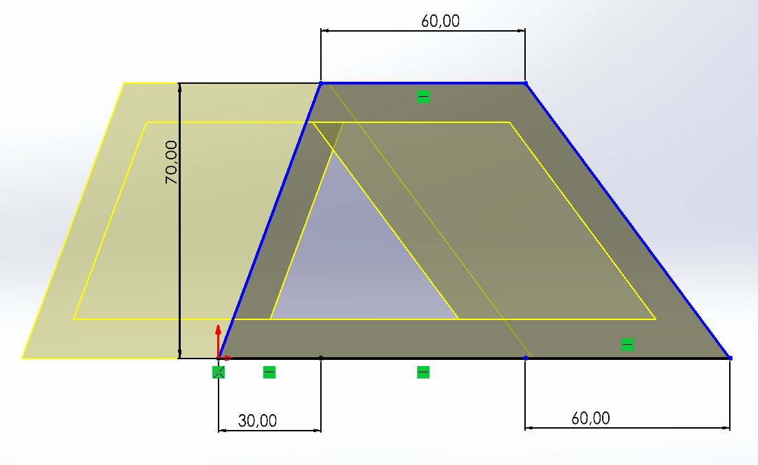
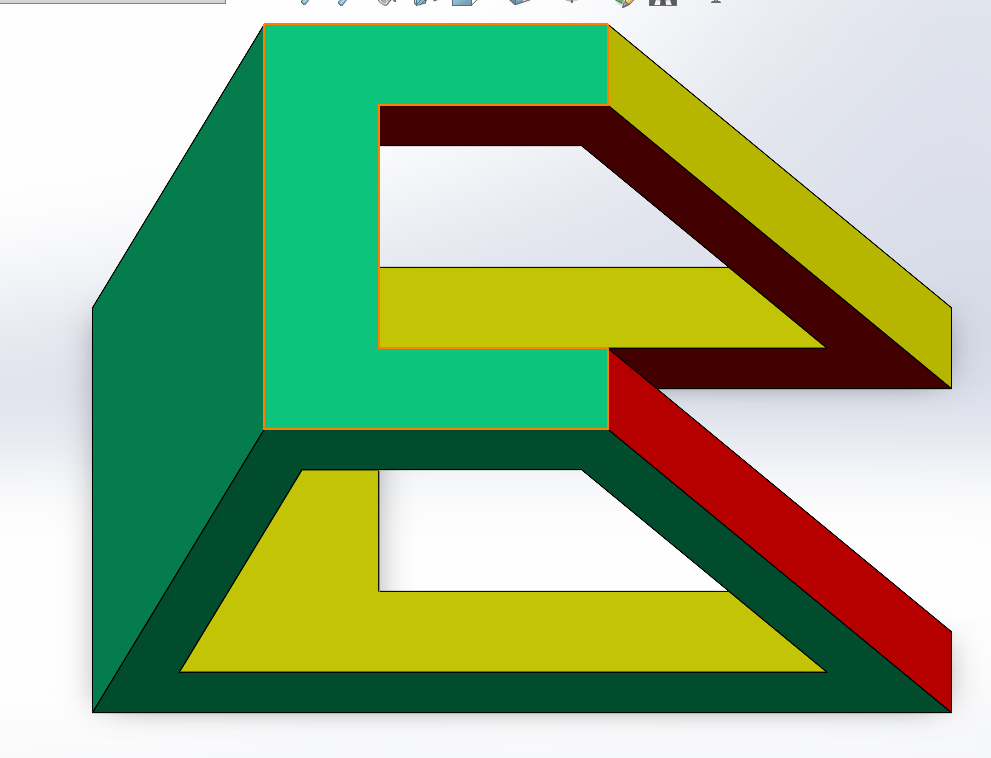
Part 1
| 2D View | 3D View |
|---|---|
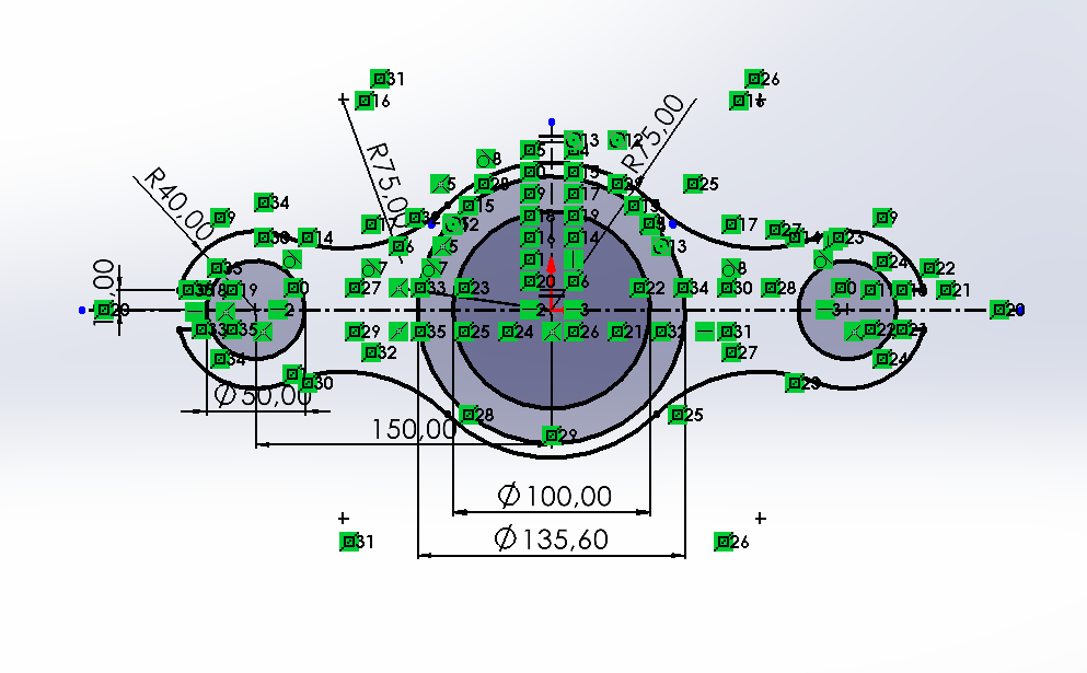 | 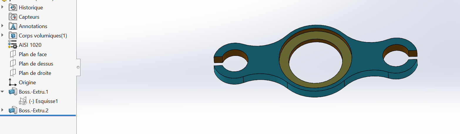 |
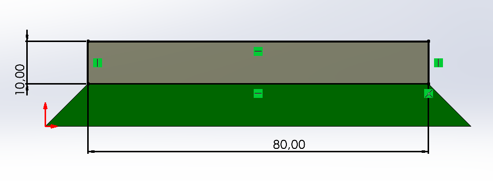
Part 2
| 2D View | 3D View |
|---|---|
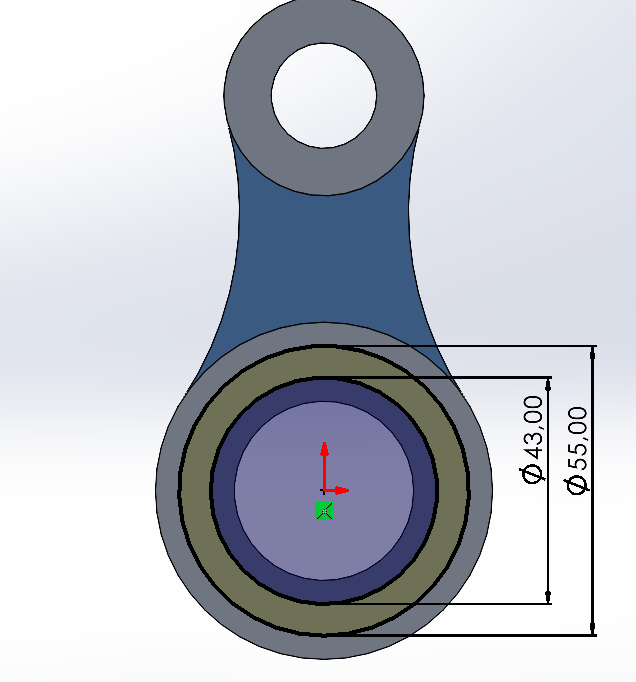 | 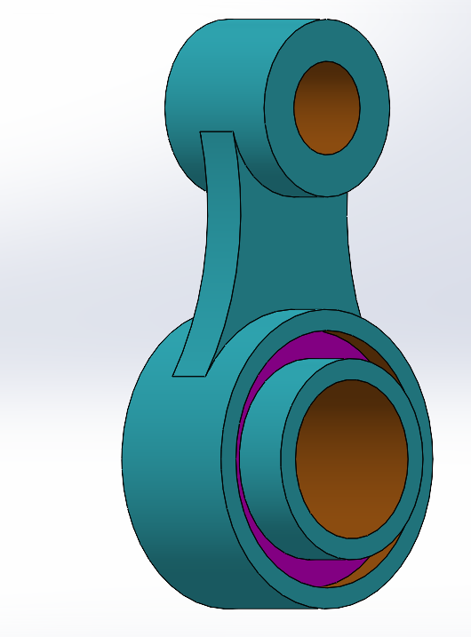 |
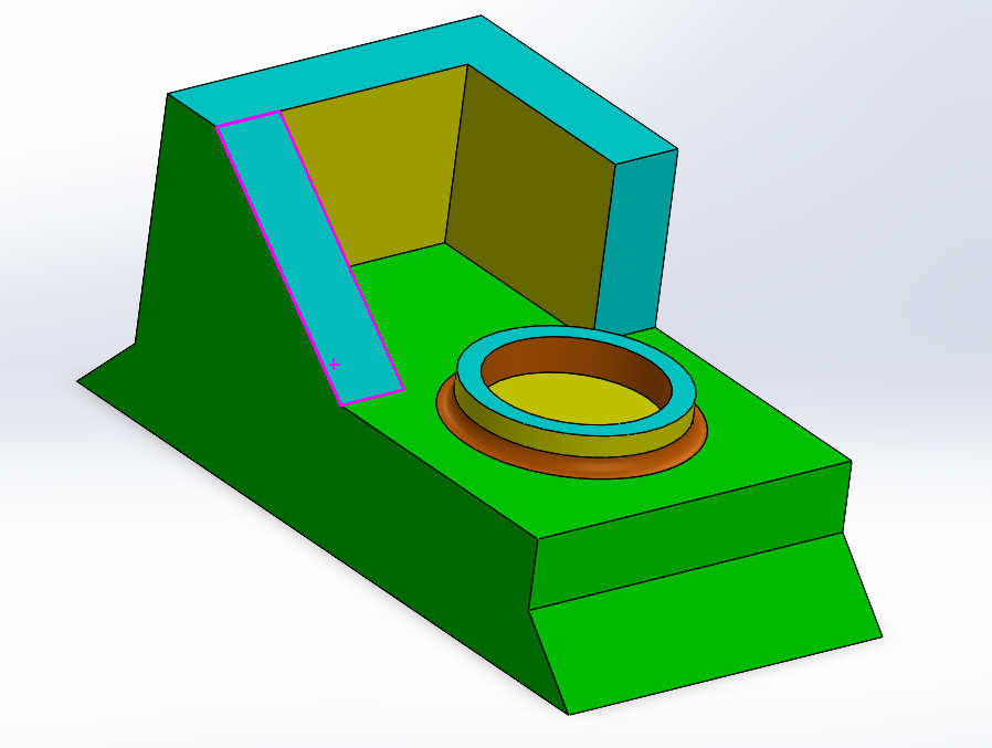
Part 3
| 2D View | 3D View |
|---|---|
 |  |
Part 4
| 2D View | 3D View |
|---|---|
 |  |
Final assembly
SolidWorks 2025 source files
These visual elements facilitate the technical reading of the project and serve as proof of modeling within the TRC2K25 framework.
Conclusion
This test allowed us to validate our ability to:
- Model precise mechanical parts
- Apply functional materials and constraints
- Perform realistic assembly under constraints
- Evaluate properties such as mass and center of gravity
This project constitutes a solid foundation for more complex mechanical designs within the TRC2K25 framework.