Final Test Electronic: Intelligent Conveyor System
Integration of electronic concepts for an automated sorting conveyor system with object detection and color sorting.
Introduction
This document presents the electronic implementation of the intelligent waste sorting conveyor system. The system uses a modular architecture with distinct functional blocks for power supply, detection, processing and actuation.
Main components
- Arduino Nano (ATmega328P) - System core
- ESP8266MOD-12 - WiFi communication
- 7805 and 7812 regulators - Power management
- Photoresistor + KY-008 - Object detection
- 12V stepper motor + L298N - Conveyor movement
- Servomotor - Sorting mechanism
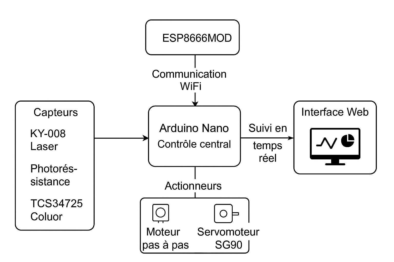
Fig. 1 - Overall view of the electronic system
System architecture
Functional diagram
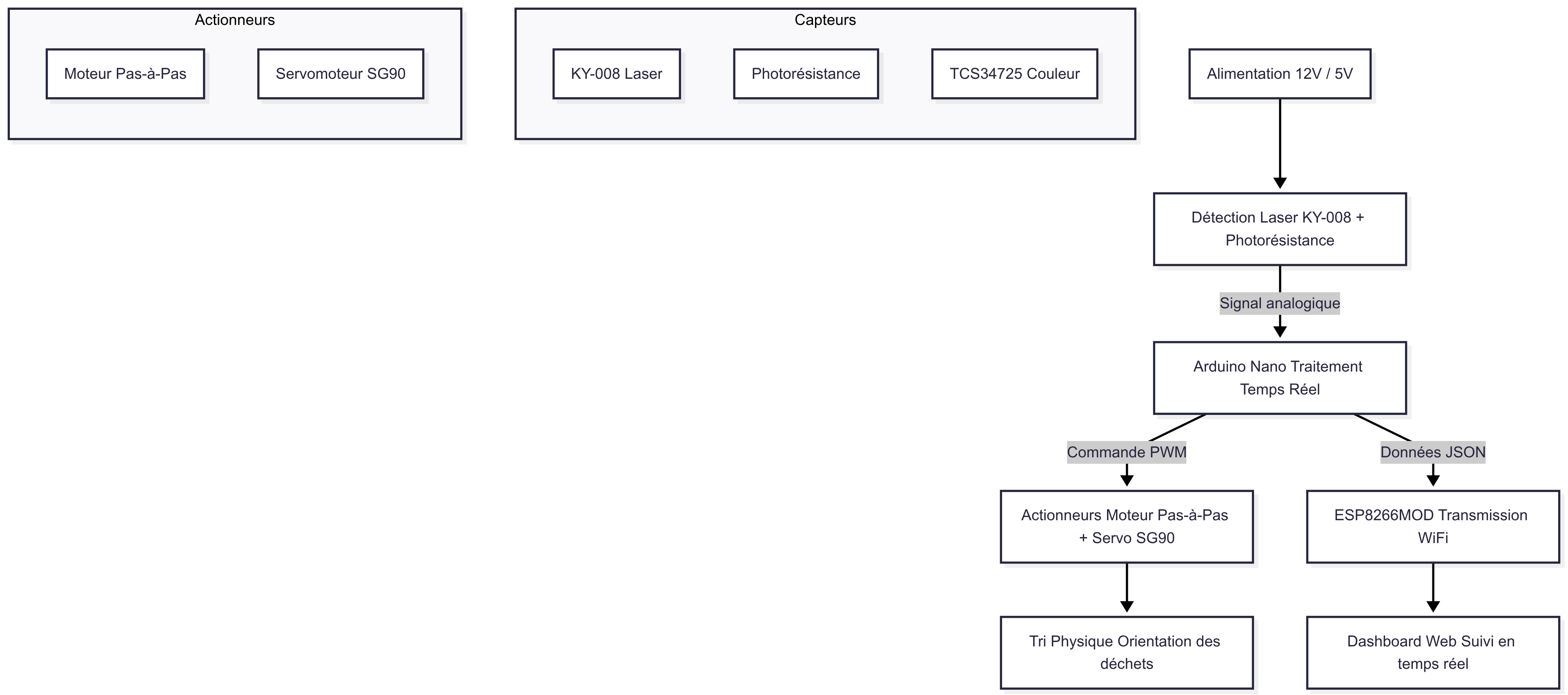
Functional description
Power supply
- Conversion of battery voltage to 12V for motors and 5V for logic circuits with precise regulation
Object detection
- KY-008 laser barrier with photoresistor for precise detection to ±1mm
Real-time processing
- Arduino Nano with optimized algorithm for latency < 5ms
Data flow
- The sensor sends an analog signal (0-5V)
- The Arduino performs ADC conversion and processing
- If positive detection → PWM command to actuators
- JSON transmission via WiFi to dashboard
- If no detection → Neutral position
Technical specifications
| Specification | Value |
|---|---|
| Sampling frequency | 200Hz |
| Detection accuracy | ±1mm |
| Processing latency | <5ms |
| WiFi throughput | 54Mbps |
Electronic components
Complete list of components
| Component | Reference | Quantity | Main function | Key characteristics |
|---|---|---|---|---|
| Arduino Nano | ATmega328P | 1 | Main controller | 16MHz, 32KB Flash, 14 I/O, 8 analog |
| WiFi module | ESP8266MOD-12 | 1 | Wireless communication | 802.11 b/g/n, UART, 80mA TX |
| 12V regulator | LM7812 | 1 | Motor power | 1A max, TO-220, 14-35V input |
| 5V regulator | LM7805 | 1 | Logic power | 1A max, TO-220, 7-25V input |
| Photoresistor | GL5528 | 1 | Light detection | 10kΩ (bright), 1MΩ (dark) |
| Laser module | KY-008 | 1 | Object detection | 650nm, 5mW, 50cm range |
| Stepper motor | 28BYJ-48 | 1 | Conveyor movement | 12V, 2048 steps/rev, 3.5kg.cm |
| Motor driver | L298N | 1 | Motor control | 2A/channel, 46V max, dual H-bridge |
| Servomotor | SG90 | 1 | Sorting mechanism | 180°, 4.8-6V, 0.1s/60° |
| Battery | Li-ion 4S | 1 | Mobile power | 14.8V, 2000mAh, 4A max |
Power supply
Main power circuit
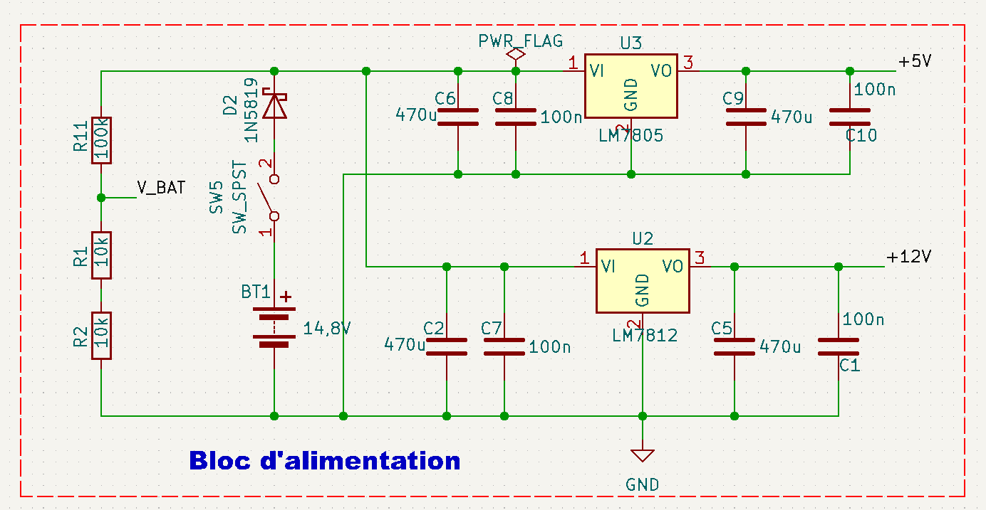
Fig. 3 - Power circuit schematic
This circuit provides the necessary voltages for all components:
- Lithium 4S 14.8V battery: Main energy source
- 7812 regulator: Stabilizes voltage at 12V for stepper motor and Arduino NANO via VIN pin
- 7805 regulator: Provides 5V for sensors and servomotors
- Protections:
- Protection diode against polarity reversal
- Stabilization capacitors (475µF + 100nF)
Input block
Complete functional schematic
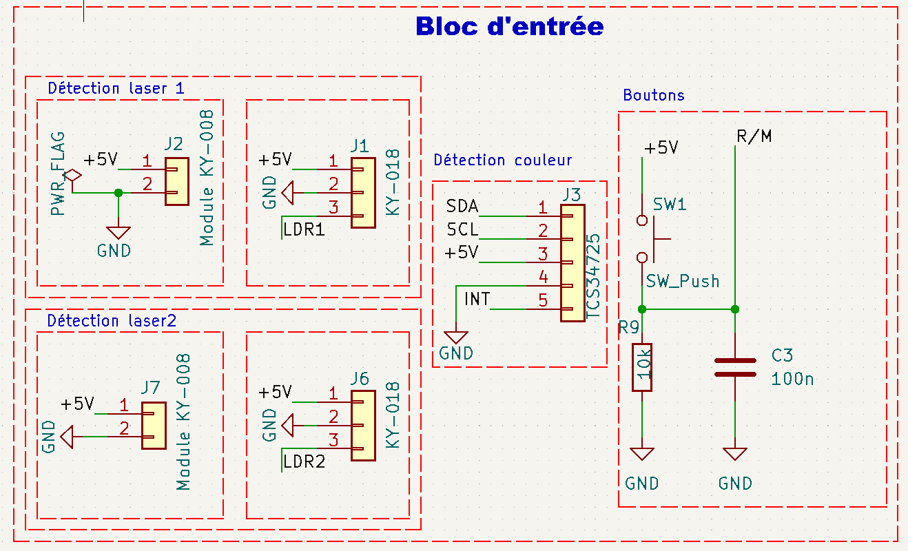
Fig. 4 - Complete architecture of the input block
Processing block
Central architecture
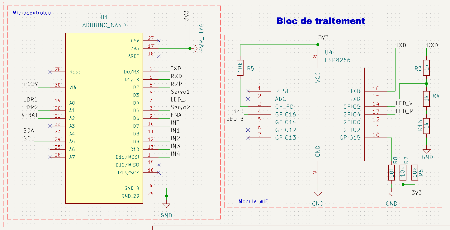
Fig. 5 - Functional schematic of the processing block
Output block
Actuator schematic
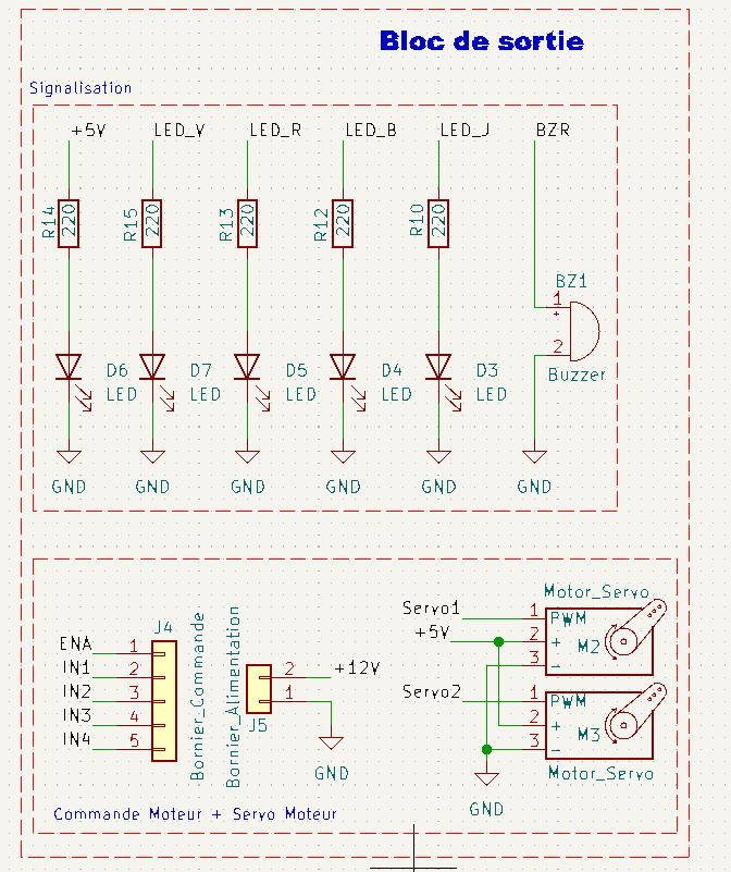
Fig. 6 - Architecture of actuation systems
Complete schematic
Main circuit
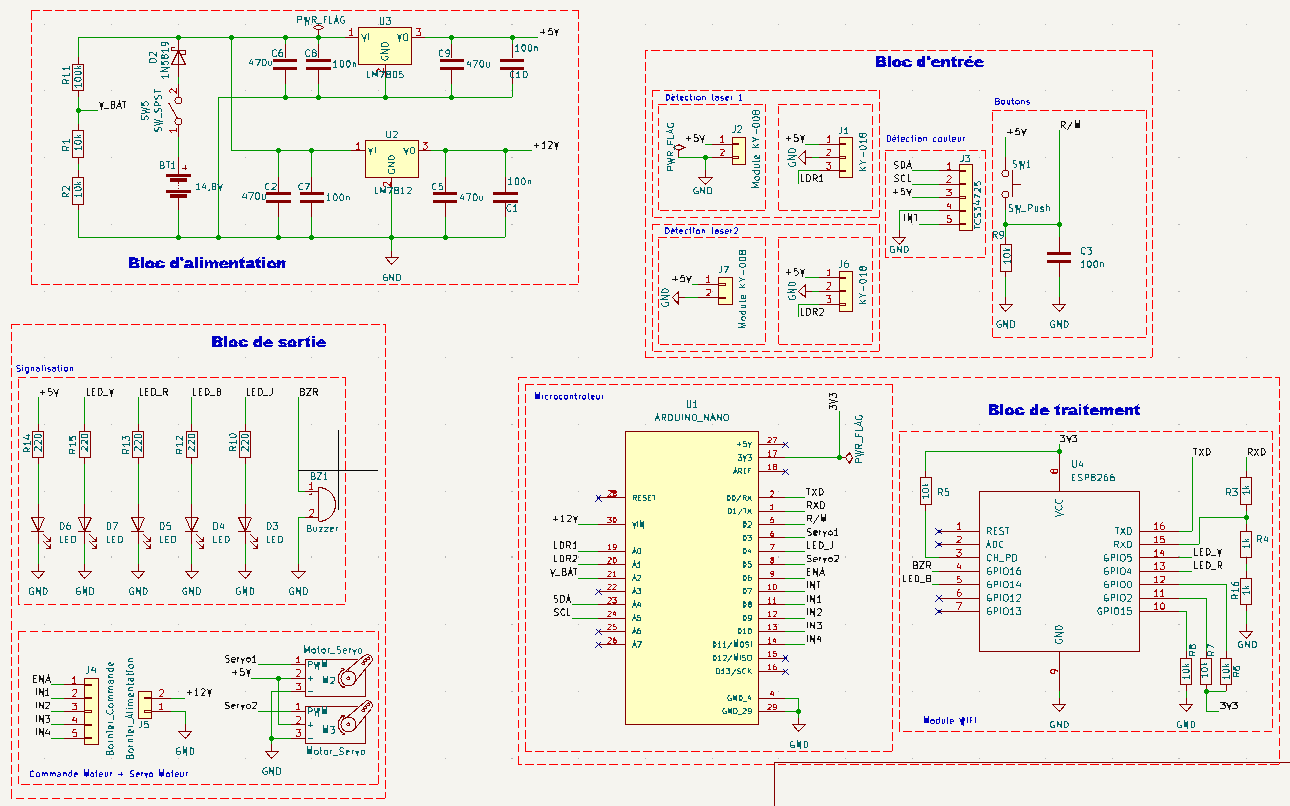
Fig. 7 - Complete system schematic (click to enlarge)
Final PCB
PCB layout
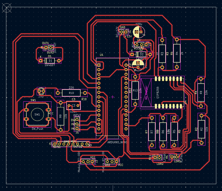
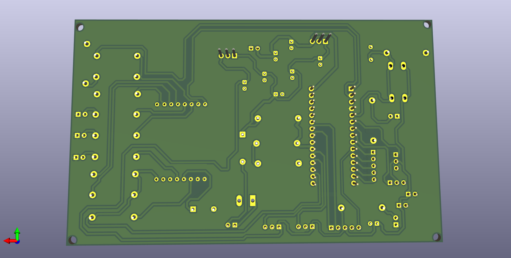
Fig. 8 - PCB layout
Top layer view
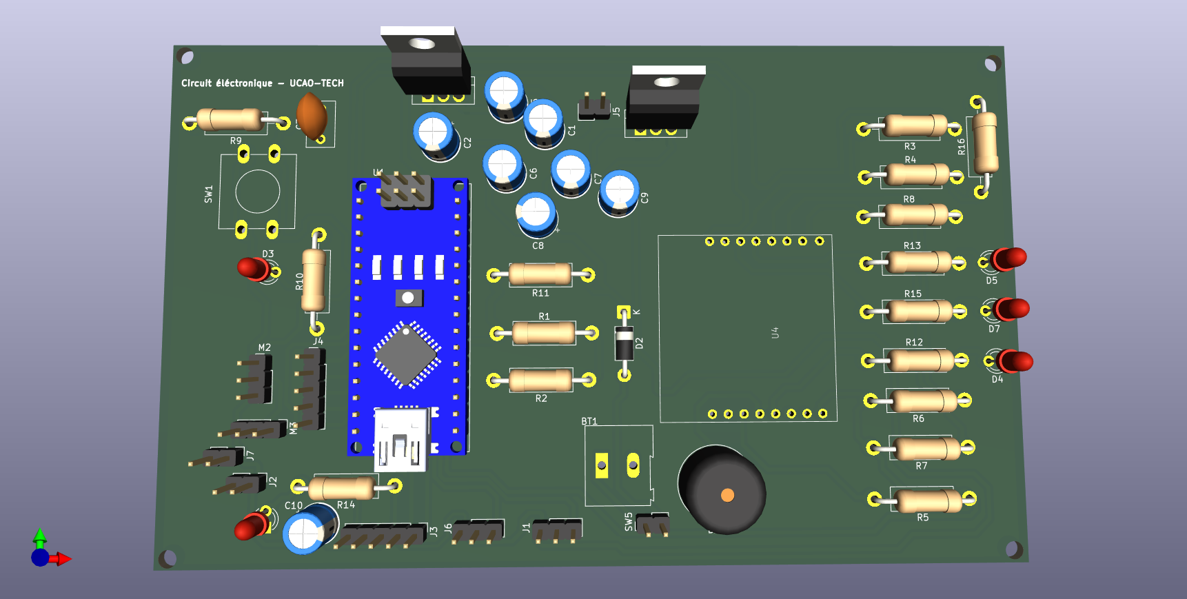
Fig. 9 - Top layer viewPCB top view
Physical prototype
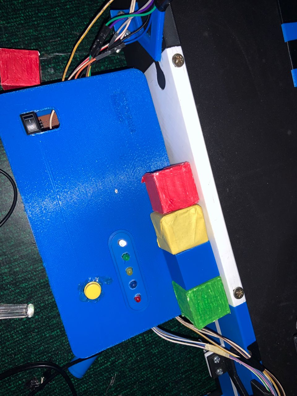
Fig. 11 - Overall prototype view
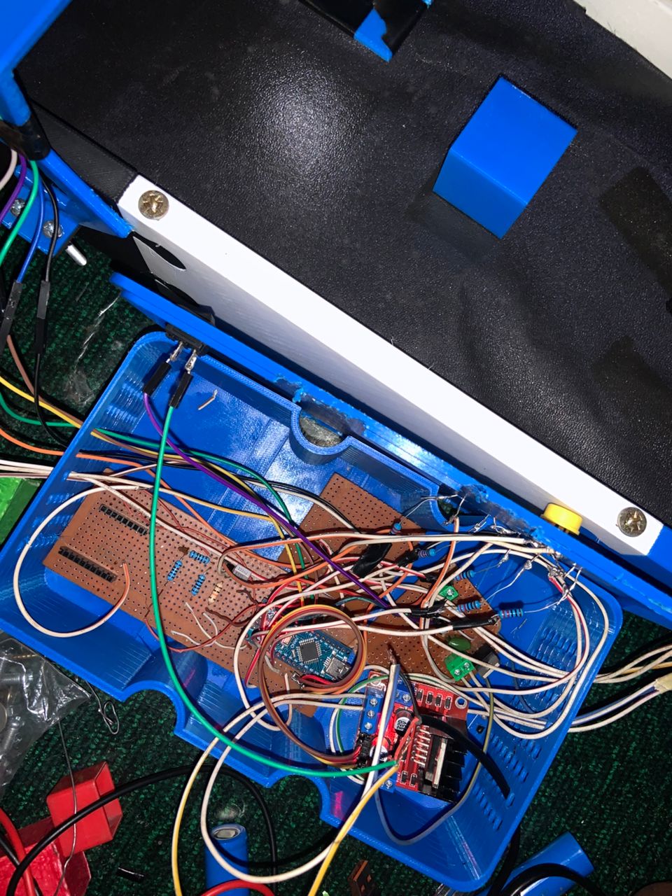
Fig. 12 - Interconnection details
Software implementation
Configuration, Setup and Loop
// === Pin definitions ===
#define START_PHOTO_PIN A1
#define STOP_PHOTO_PIN A2
#define BUTTON_PIN 12
#define LED_PIN 7
#define IN1 8
#define IN2 9
#define IN3 10
#define IN4 11

#include <Wire.h>
#include <Adafruit_TCS34725.h>

Adafruit_TCS34725 tcs = Adafruit_TCS34725();
const int bleu = 3;
const int rouge = 4;
const int jaune = 5;
const int vert = 6;

const int threshold = 450;
const int stepDelay = 5;
const unsigned long longPressTime = 2000;

bool systemActive = false;
unsigned long buttonPressTime = 0;

void setup() {
  pinMode(IN1, OUTPUT);
  pinMode(IN2, OUTPUT);
  pinMode(IN3, OUTPUT);
  pinMode(IN4, OUTPUT);
  pinMode(BUTTON_PIN, INPUT);
  pinMode(LED_PIN, OUTPUT);

  stopMotor();
  digitalWrite(LED_PIN, LOW);

  Serial.begin(9600);
  Serial.println("System ready. Waiting...");

  if (tcs.begin()) {
    Serial.println("TCS34725 sensor detected!");
    tcs.setInterrupt(false);
  } else {
    Serial.println("TCS34725 sensor error");
    while (1);
  }

  pinMode(bleu, OUTPUT);
  pinMode(rouge, OUTPUT);
  pinMode(jaune, OUTPUT);
  pinMode(vert, OUTPUT);

  digitalWrite(rouge, LOW);
  digitalWrite(bleu, LOW);
  digitalWrite(jaune, LOW);
  digitalWrite(vert, LOW);
}

void loop() {
  Serial.print("Start sensor: ");
  Serial.print(analogRead(START_PHOTO_PIN));
  Serial.print(" | Stop sensor: ");
  Serial.println(analogRead(STOP_PHOTO_PIN));

  handleButton();

  if (!systemActive && detectStartSensor()) {
    activateSystem("START detection → Activation");
  }

  if (systemActive && detectStopSensor()) {
    deactivateSystem("STOP detection → Stop");
  }

  if (systemActive) {
    stepMotor();
    delay(stepDelay);

    String color = detectColorTCS34725();
    Serial.print("Detected color: ");
    Serial.println(color);
  }
}
Serial communication with ESP8266 for web interface
The Arduino Nano transmits sorting data to the ESP8266 NodeMCU via serial link.
This data is then displayed on the web dashboard, including:
- Color counters
- Sorting position
- Time of last sort
Arduino code example
// Global counter declarations for each color
int compteurRouge = 0;
int compteurVert = 0;
int compteurJaune = 0;
int compteurBleu = 0;

/**
 * @brief Sends sorting data to ESP8266 for display on web interface
 *
 * @param couleur The color of the detected object ("Rouge", "Vert", "Jaune", "Bleu")
 * @param position The sorting position of the object on the conveyor
 */
void envoyerDonneesWeb(String couleur, int position) {
  // Increment corresponding counter
  if (couleur == "Rouge") {
    compteurRouge++;
  } else if (couleur == "Vert") {
    compteurVert++;
  } else if (couleur == "Jaune") {
    compteurJaune++;
  } else if (couleur == "Bleu") {
    compteurBleu++;
  }

  // Build and send JSON via serial port
  Serial.print("{\"couleur\":\"");
  Serial.print(couleur);
  Serial.print("\",\"position\":");
  Serial.print(position);
  Serial.print(",\"compteurs\":{\"Rouge\":");
  Serial.print(compteurRouge);
  Serial.print(",\"Vert\":");
  Serial.print(compteurVert);
  Serial.print(",\"Jaune\":");
  Serial.print(compteurJaune);
  Serial.print(",\"Bleu\":");
  Serial.print(compteurBleu);
  Serial.println("}}");
}

void setup() {
  // Serial communication initialization
  Serial.begin(9600);
}

void loop() {
  // Example test: send a color and position every 5 seconds
  envoyerDonneesWeb("Rouge", 1);
  delay(5000);
}
[📥 Download complete code (.rar)] (#link)
Tests and validation
Test plan:
- Power test: Measure 12V, 5V and 3.3V voltages under load
- Detection test: Verify object detection at different distances
- Color test: Validate identification of 4 colors
- Motor test: Verify precise conveyor movement
- Sorting test: Validate sorting mechanism for each color
- WiFi test: Verify data transmission to web interface
Demonstration video
See the complete system operation videoElec videoDetection test
Downloads
Conclusion
Technical summary
The electronic system meets the project requirements:
- Reliable object and color detection
- Precise actuator control
- Stable communication with web interface
- Sufficient autonomy (>3 hours)
Future perspectives
Possible improvements:
- Addition of backup battery
- Integration of additional sensors
- Energy consumption optimization
- Fully wireless version